Model CD1, single speed wire rope electric hoist is small-sized lifting equipment, which can be mounted on single beam, overhead, gantry and jib cranes, with slight modification; it can also be used as a winch.
MORE
HOT PRODUCTS

Model CD1, single speed wire rope electric hoist is small-sized lifting equipment, which can be mounted on single beam, overhead, gantry and jib cranes, with slight modification; it can also be used as a winch.
MORE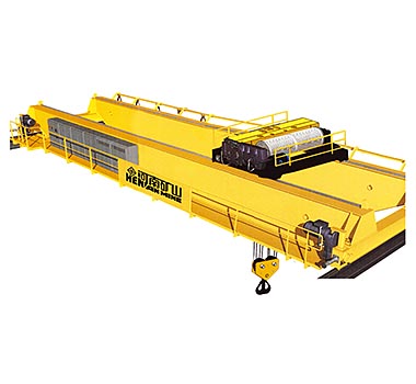
HNKS Crane Co., Ltd is one of Chinese leading manufacturers of many kinds’ cranes. Such as overhead Crane, gantry crane, European crane, tire rubber crane, metallurgy crane, portal crane, jib crane, electric hoist, grab bucket, etc.Welcome to Changyuan ...
MORE
Gantry Crane actually is overhead crane with legs, it’s normally worked outdoors, and also sometimes indoors
MORE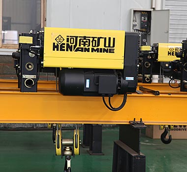
European wire ripe electric hoist adopts the European FEM design standards with advanced concept, the operation is simple, convenient and working is safety and efficient and meet the low noise, energy conservation and environment protection requiremen...
MORERail-Mounted Container Gantry Crane for Railway Port | Henan Mine Crane
2022-08-25
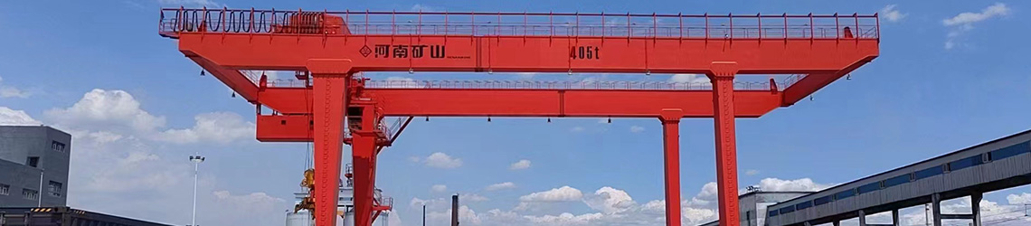
The Rail-Mounted Gantry Crane (RMG) is a piece of container handling equipment that operates on rails; it is primarily used in ports, railway freight yards, and container depots for the loading, unloading, transport, and stacking of containers.
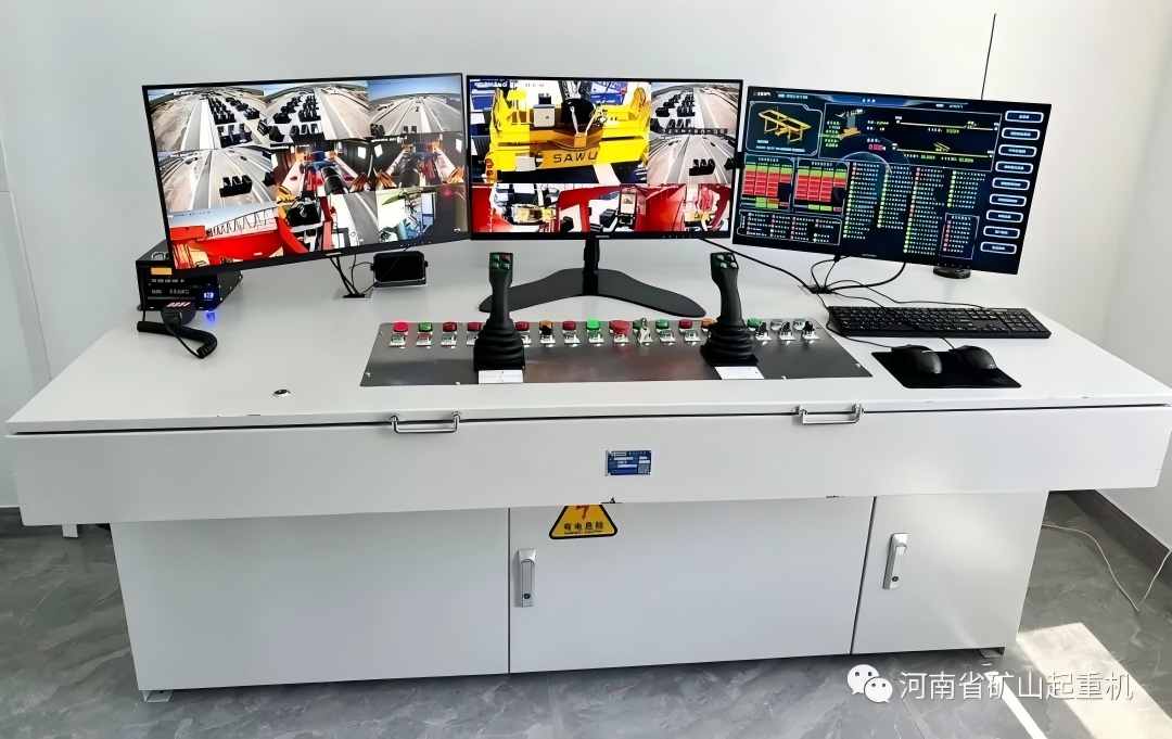
This crane utilizes a Schneider variable-frequency drive system and a Siemens PLC control system, featuring remote monitoring (RCMS) and remote operation capabilities. Additionally, it is equipped with anti-sway and anti-lift (container truck) protection systems. Through automatic container locating and intelligent control, the system enables spreader zero-position monitoring and automatic spreader guidance, ensuring precise positioning during container handling. It adapts to complex operational environments, effectively boosting container handling efficiency and meeting the daily lifting and transport requirements of Wanli Inland Port.
| Lifting capacity of the spreader | t | 40.5 | |
| gauge | m | 40 | |
| Effective cantilever length | m | 7.5/7.5 | |
| Lifting height | m | ≥18.2 | |
| Lifting speed | Fully loaded | m/min | ≥20 |
| Unloaded | m/min | ≥40 | |
| Travelling of crab | Fully loaded | m/min | ≥80 |
| Unloaded | m/min | ≥100 | |
| Travelling of trolley | Fully loaded | m/min | ≥50 |
| Unloaded | m/min | ||
| Spreader rotation angle | ◦ | ±5 | |
| Power supply method | cable reel | ||
| Remark | Customization available to meet customer needs | ||
The steel structure of rail-mounted container gantry crane typically employs a box-girder design; however, a truss structure may be used to reduce the overall weight of the machine, albeit at a higher manufacturing cost.
Depending on the support method of the gantry legs, the overall structure commonly adopts either a "Π" shape or a "U" shape. In the "Π" configuration, both the rigid and flexible legs are "Π"-shaped; the lateral stiffness of the two main girders, as well as the strength and stiffness of the legs themselves, are achieved through the structural rigidity at the connections between the legs and the upper crossbeam. In the "U" configuration, the structural integrity relies on the connection stiffness between the legs and the lower crossbeam.
1. Main girder structure. The main girder structure consists of two box-section girders supported by rigid and flexible legs. Box girders with offset rails are commonly used; to ensure that flange welds avoid high-stress zones caused by wheel loads, the rail-bearing section utilizes a T-shaped steel profile welded to the main girder's top plate and load-bearing web. High-strength bolts or welding are used to connect the main girder to the rigid leg, while a hinged connection is employed for the flexible leg; for ease of installation, high-strength bolted connections are generally used to join the main girder to the end carriages.
2. Gantry leg structure. Both rigid and flexible gantry legs utilize a box-girder structure; for rail-mounted container gantry cranes with small to medium spans, both legs are designed as rigid legs. For "Π"-shaped legs, strength and rigidity along the gantry travel direction are achieved through a rigid connection between the legs and the top crossbeam; for "U"-shaped legs, this is achieved through a rigid connection between the legs and the bottom crossbeam, while strength and rigidity along the trolley travel direction are ensured by a rigid connection between the main girder and the rigid legs. In small- to medium-span cranes, skewing forces exerted on the legs and main girder—caused by a lack of synchronization between the two sides of the gantry—are accommodated by the rigid connection at the rigid leg and the single-degree-of-freedom hinged connection at the flexible leg. For long-span cranes, the connection between the flexible leg and the main girder employs a three-degree-of-freedom hinged connection, supplemented by a synchronization monitoring system.
3. Trolley structure. The structure of the traversing trolley varies depending on whether the hoisting mechanism is of the wire rope drum type or the telescopic rigid frame type; typically, a composite structure comprising box girders and plate-truss elements is employed. The trolley structure is designed to accommodate the layout of the hoisting and traversing mechanisms, ensuring it can withstand the transmitted loads during operation while maintaining adequate rigidity. Components such as the operator's cabin, electrical control cabinet, anti-sway system, and cable festoon assembly are mounted onto the trolley structure.
4. Auxiliary structures. These include the electrical room structure located on one side of the main girder, as well as escalators, walkways, and maintenance platforms.
With the exception of the specialized selection of the hoisting mechanism, the trolley and gantry travel mechanisms of rail-mounted container gantry cranes are essentially the same as those of other bridge and gantry cranes.
1. Hoisting mechanism. There are two types of hoisting mechanisms: the wire-rope drum type—which is essentially the same as that used on rubber-tired gantry cranes (RTG) —and the rigid telescopic type, which resembles the hoisting mechanism of metallurgical tong-handling bridge cranes used in steel mills.
(1) The wire-rope drum-type hoisting mechanism consists of a DC or AC motor, a gear coupling, a disc or block brake, a medium-hard tooth-surface gear reducer, a gear coupling connecting the reducer to the drum, a double-drum assembly, and bearing housings. The hoisting wire rope, sheaves, and spreader sheave block form the reeving system.
(2) The rigid telescopic hoisting mechanism may consist of a wire rope drum hoist, a hydraulic cylinder hoist, or a counterweighted rack-and-pinion hoist, combined with a telescopic steel guide structure. The wire rope drum hoist features a simple design, with basic components similar to those of other hoisting mechanisms; however, due to the inherent rigidity of the steel structure, the hoisting mechanism can be split into two separate units, facilitating layout flexibility. The hydraulic cylinder hoist operates smoothly and has a simple structure, though it demands higher standards for maintenance.
2. Trolley traversing mechanism. The trolley traversing mechanism consists of a DC or AC motor, a gear coupling, a block or disc brake, a medium-hard tooth-surface gear reducer, a low-speed gear coupling, and wheels with their supports. The drive mechanism is generally arranged either parallel to or perpendicular to the trolley track. The number of driven wheels is determined based on the requirement to prevent slippage; modern designs predominantly utilize an all-wheel drive configuration.
3. Bridge travel mechanism. The bridge travel mechanism typically employs three- or four-wheel bogies, the configuration of which is determined by the magnitude of the wheel load. Its construction and form are similar to those of other types of cranes; if an open-gear drive is used for the bogie, the system comprises a DC or AC motor, gear coupling, brake, medium-hardened gear reducer, open gears, wheels, and wheel supports. Alternatively, if an enclosed drive is used, the reducer output shaft connects directly to the wheel axle for direct transmission, though this requires a slightly higher gear reduction ratio. Given the high travel speed, electrical control systems with excellent speed-regulation capabilities—such as thyristor DC voltage/speed control, AC variable-frequency drive (VFD), or AC stator voltage control—are generally selected to prevent wheel slippage during acceleration and braking.
The RMG operates by achieving precise positioning and handling of containers within a three-dimensional coordinate system (X-axis: gantry travel direction; Y-axis: trolley travel direction; Z-axis: hoisting height) and can interact with container trucks and rail-mounted cranes.
1.Instruction Receipt: Instructions are received from the terminal operating system, specifying the target container's location in the yard by bay (gantry crane position), row (trolley position), and tier.
2.Gantry Positioning: The gantry drive mechanism starts and moves to the designated bay position; the positioning system provides real-time feedback and ensures precise stopping.
3.Trolley positioning: The hoisting trolley moves laterally to a position above the designated column.
4.Spreader Alignment and Engagement: The hoisting mechanism lowers the spreader; assisted by guide plates (or a vision system), the twistlocks are precisely aligned with the container's corner castings. Once the spreader signals "container contact," the twistlocks automatically rotate to lock.
5.Hoisting and Anti-sway: After confirming the lock is engaged, vertically hoist the container to a safe height while the control system suppresses spreader sway.
6.Horizontal transport: The gantry and trolley operate in coordination to transport containers to the target location (such as above a container truck or a railway wagon).
7.Alignment and Container Placement: After precise positioning, the container is slowly lowered; the twistlocks automatically unlock, the spreader rises, and the operation is completed.
The entire process is monitored and operated by the driver from the cab, or executed fully automatically by the system.
| High degree of automation | RMG enables automated operation with a human-to-machine ratio of up to 1:6 and an overall efficiency of up to 250 m/s per hour. It is equipped with various automated systems, such as a truck positioning system, a container area scanning system, and a trolley automatic deviation correction system, ensuring precise and efficient operation. |
| Stable structure | The system employs an off-center box girder structure, with the main beam fabricated as a single piece to ensure a smooth arch curve and reduce trolley rail wear. Its robust design minimizes swaying and facilitates operation and box girder alignment. |
| Stable operation | The operating mechanism adopts advanced technologies, such as a three-in-one geared motor, which is lightweight, easy to disassemble and assemble, and has low maintenance costs. |
| Safe and reliable | Equipped with multiple safety protection systems, such as anti-lifting system for trucks, anti-collision system for truck cabs, electronic fence for work area, and anti-bowling system, to ensure operational safety. |
| Stable and reliable structure | Composed of two columns and a crossbeam, the stable portal frame is made of high-strength materials and features a robust design, providing high load-bearing capacity and wind resistance, making it suitable for long-term operation in complex environments. |
| High load-bearing capacity | The lifting capacity ranges from a few tons to hundreds of tons, which can meet the needs of large-scale material handling. |
| Wide range of work | With a large span and lifting height, it can cover a wide working area and adapt to different working environments. |
| Precise positioning capability | Equipped with a precise positioning system, it can achieve accurate positioning whether lifting vertically or moving horizontally. |
| High customizability | It can be customized according to the work site, load requirements and specific application needs. |
| High degree of automation | Some equipment is equipped with an automated control system, which enables unmanned operation, improving efficiency and safety. |
| Good safety performance | Equipped with safety devices such as overload protection, travel limit, emergency stop and anti-collision to ensure safe operation. |
| Strong environmental adaptability | Suitable for various working environments, including indoor, outdoor, dry, and humid conditions. |
| Easy to maintain | Key components are easy to repair and replace, reducing maintenance time and costs. |
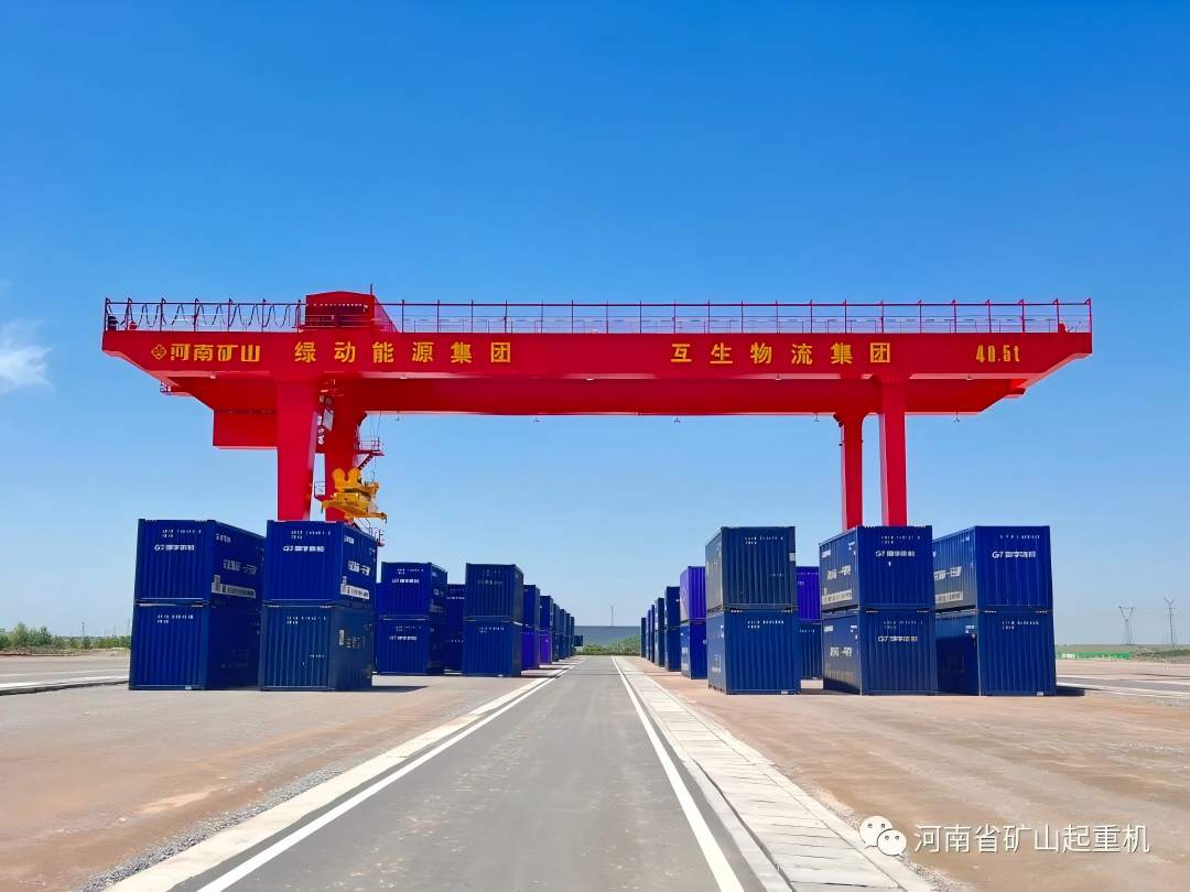
Application scenario: Rear storage yard of large sea and river container terminals.
Main functions: To work with quay cranes (QC) for the longitudinal and lateral stacking, overturning, and loading/unloading of containers onto trailers. Due to its large span and high lifting height, it can greatly increase the storage density of the yard.
Application scenarios: railway freight hubs, multimodal transport stations.
Main function: To enable rapid and direct loading of containers between railway flatcars and road trucks (or yard surfaces). RMGs can cross multiple railway tracks and road lanes, making them a core piece of equipment for achieving seamless "rail-road" connections.
Application scenarios: Bonded logistics centers in inland cities and large-scale comprehensive logistics hubs.
Primary Function: Used for lifting operations involving container distribution, temporary storage, transshipment, and customs-supervised inspection; it alleviates storage pressure at coastal ports and enhances turnover efficiency at inland logistics hubs.
Application scenario: Highly automated smart ports.
Primary Function: Equipped with automated control systems (such as laser scanning, DGPS positioning, and remote control capabilities), it eliminates the need for manual operation, enabling fully automated, unmanned operations in container yards, thereby significantly reducing labor costs and enhancing safety.
Rail-mounted gantry crane (RMG) and rubber-tired gantry crane (RTG) are both core handling equipment for container yards. While both are capable of container stacking and loading/unloading operations involving container trucks, they differ fundamentally in terms of operating infrastructure, operational characteristics, cost structures, and suitability for specific scenarios. RMG cranes operate on fixed rails, prioritizing stability and efficiency, whereas RTG cranes move on rubber tires, emphasizing flexibility and mobility. These two types of equipment are suited to container terminals of varying scales and operational models; selecting the right equipment requires a comprehensive assessment based on yard characteristics, throughput requirements, and site conditions.
| Comparison dimensions | Rail-mounted gantry crane (RMG) | Rubber-Tired Gantry Crane (RTG) |
| Operational Model and Site Infrastructure | Operational carrier: Travels along a preset, fixed track. | Operational carrier: Relies on rubber tires for load-bearing and movement. |
| Infrastructure requirements: Concrete track foundations must be cast in advance; the volume of work is substantial. | Infrastructure requirements: No fixed tracks required; the site simply needs to be paved and level, ensuring a low barrier to deployment. | |
| Movement characteristics: Range strictly confined to the track section; movement across sections is not permitted; boundaries are clear and well-defined. | Mobility features: Capable of freely traversing different container zones and adjusting positioning at any time, without being constrained by fixed routes. | |
| Operational Characteristics and Suitable Scenarios | Operational rhythm: Constant path, fixed alignment process, and stable overall efficiency for continuous stacking. | Operational rhythm: Transitions are flexible, but aligning individual containers takes slightly longer, and efficiency depends on the quality of scheduling. |
| Suitable for: Continuous operations in fixed container zones at high-throughput hub yards. | Suitable Scenarios: Small to medium-sized terminals or yards, phased operations, operations in dispersed container zones, and temporary storage yard activities. | |
| Cost Structure and Input-Output | Initial investment: Requires track infrastructure; overall upfront deployment costs are relatively high. | Initial Investment: No infrastructure investment required; operations can commence immediately upon equipment procurement, resulting in minimal upfront financial pressure. |
| Post-commissioning operation: Primarily powered by the grid, resulting in relatively low energy costs per unit of operation. | Post-delivery operations: Predominantly diesel or hybrid powertrains; high fuel consumption and tire wear result in higher daily operating costs. | |
| Key consumption: Routine maintenance focuses on the upkeep of tracks and travel components. | Core consumption: fuel consumption, tire wear. | |
| Operations, Maintenance, and Site Adaptation | Key maintenance and management areas: Fixed operational points (e.g., rail wear, cable reels) with a high degree of standardization. | Key maintenance and management areas: Numerous moving parts (tire wear, powertrain, etc.) and relatively complex maintenance procedures. |
| Site adaptability: Constrained by the track, it cannot accommodate ad-hoc adjustments. | Site adaptability: Capable of rapid relocation and redeployment, with exceptional ability to handle changes in venue. | |
| Long-term planning: Suitable for stable, fixed storage yards requiring long-term planning. | Long-term planning: Adaptation of renovated or expanded facilities; temporary staging yards. |
The rail-mounted container gantry crane, custom-built by Henan Mine Crane for Wanli Land Port, will—through high-quality products and services and outstanding container yard handling performance—significantly boost the land port's container freight capacity, providing the technical and equipment support needed for its overall operations.
Moving forward, Henan Mine Crane will engage in in-depth cooperation with Ludong Energy and Husheng Logistics on the New Energy Smart Inland Port project, helping to build a modern logistics network that serves as a regional hub for the Hohhot-Baotou-Ordos-Ulanqab area—characterized by intensive efficiency, green intelligence, openness, and shared access.
